
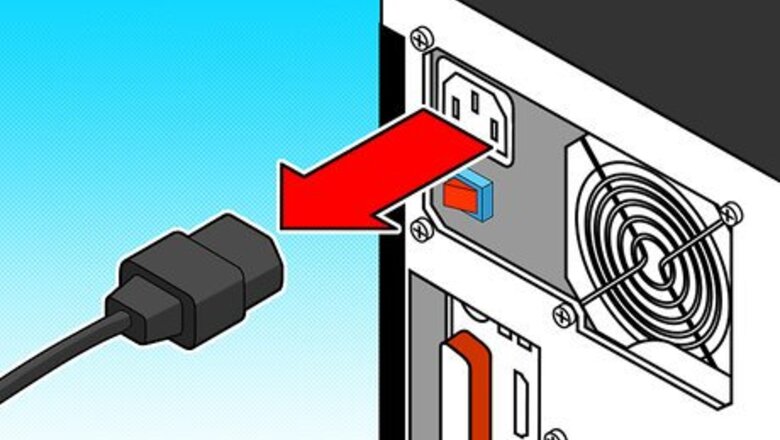
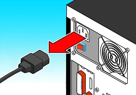
Unplug the power cord from the back of the computer.
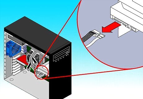
"Harvest" a power supply from a computer by opening up the case of the computer, locating the gray box that is the power supply unit, tracing the wires from the power supply to the boards and devices and disconnecting all the cables by unplugging them.
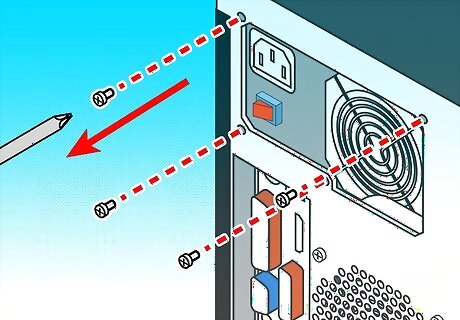
Remove the screws (typically 4) that attach the power supply to the computer case and remove the power supply.
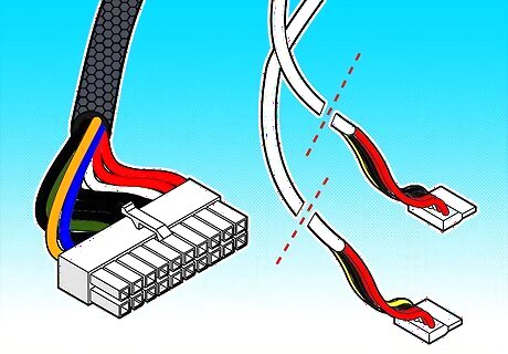
Cut off the connectors except for the large Male ATX connector that goes to the Motherboard.
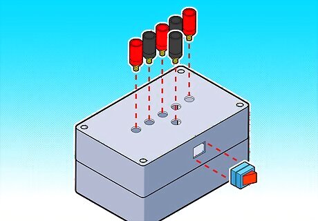
Drill the holes in your "box" and mount the binding posts, switch, and LED.
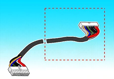
Cut your ATX extension cable in half and harvest the female side.
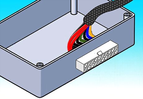
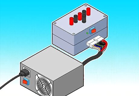
Mount the female side to your box (you will use the dremel to make the hole for this; you may want to use some epoxy to help hold it in).

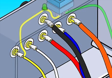
Bundle the like colored wires together, stripping them and twisting together so that each colored bundle has one connection point. You'll end up with a bundle for +12, -12, +5, -5, +3.3, ground, Power OK, Power ON.Create a 12 Volt DC Test Bench for Bullet Cameras Using an Old ATX Computer Power Supply Step 8Bullet1.jpg

Connect the POWER ON (usually GREEN) wire to one side; Connect the other side to the negative side of the LED and GROUND (so, the "out" side of the switch is connected to two wires ... the one coming "out" of the LED and the GROUND bundle).

Connect the positive side to +12V and the other side to the GROUND bundle (which is also connected to the "out" side of the switch as described above).
Connect the bundled wires to +12, -12, +5, -5, 3.3V and ground, respectively.

Connect the POWER OK (usually GRAY, but sometimes BROWN) directly to the POWER SENSING (usually PURPLE or BROWN) wire.
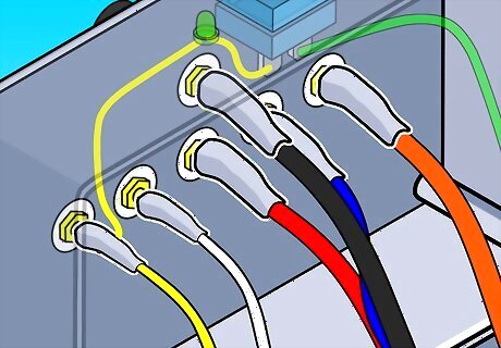
Make sure that the wire connections are insulated in heat-shrink tubing. Organize the wires with an electrical tape or zip-ties.Create a 12 Volt DC Test Bench for Bullet Cameras Using an Old ATX Computer Power Supply Step 13Bullet1.jpg
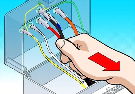
Check for loose connections by gently tugging on them. Inspect for bare wire, and cover it to prevent a short circuit. You may want to put a drop of super-glue to stick the LED to its hole. Put the cover back on.Create a 12 Volt DC Test Bench for Bullet Cameras Using an Old ATX Computer Power Supply Step 14Bullet1.jpg
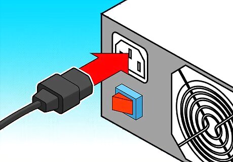
Plug the power cord into the back and into an AC socket.
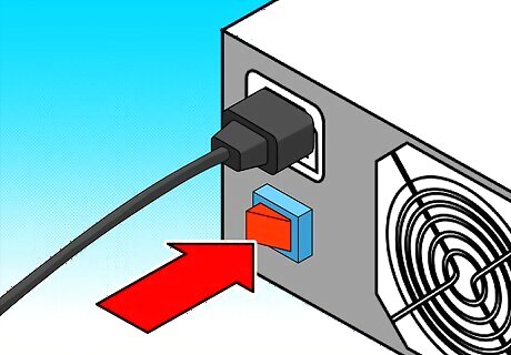
Flip the main switch on the Power Supply and check to see if the LED light comes on. If it has not, then power up by flipping the switch you placed on the front.Create a 12 Volt DC Test Bench for Bullet Cameras Using an Old ATX Computer Power Supply Step 16Bullet1.jpg
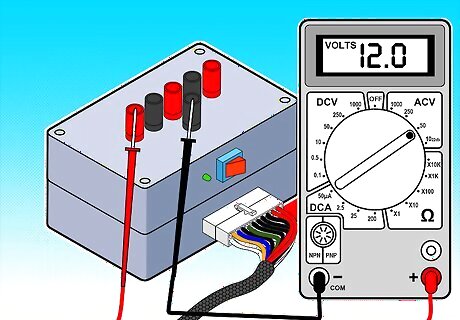
Plug in a 12V bulb into the different sockets to see if the PSU works, also check with a digital voltmeter.
Finished.


Comments
0 comment