views
Reading the Dial Settings
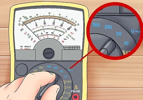
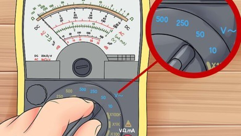
Test AC or DC voltage. In general, V indicates voltage, a squiggly line indicates alternating current (found in household circuits), and a straight or dashed line indicates direct current (found in most batteries). The line can appear next to or over the letter. The power coming from most household circuits is AC. However, some devices may convert the power to DC through a transistor, so check the voltage label before you test an object. The setting for testing voltage in an AC circuit is typically marked V~, ACV, or VAC. To test voltage on a DC circuit, set the multimeter to V–, V---, DCV, or VDC.
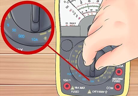
Set the multimeter to measure current. Because current is measured in amperes, it is abbreviated A. Choose direct current or alternating current, whichever the circuit you are testing is made for. Analog multimeters typically do not have the ability to test current. A~, ACA, and AAC are for alternating current. A–, A---, DCA, and ADC are for direct current.
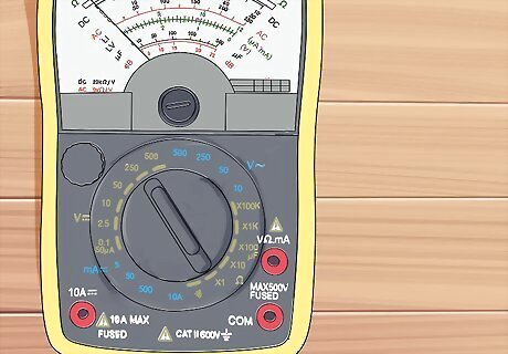
Find the resistance setting. This is marked by the Greek letter omega: Ω. This is the symbol used to denote ohms, the unit used to measure resistance. On older multimeters, this is sometimes labeled R for resistance instead.
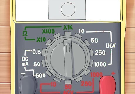
Use DC+ and DC-. If your multimeter has this setting, keep it on DC+ when testing a direct current. If you aren't getting a reading and suspect you've got the positive and negative terminals attached to the wrong ends, switch to DC- to correct this without having to adjust the wires.
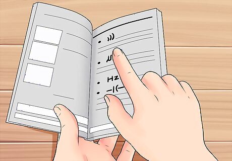
Understand other symbols. If you're not sure why there are multiple settings for voltage, current, or resistance, read the troubleshooting section for information on ranges. Besides these basic settings, most multimeters have a couple additional settings. If more than one of these marks is next to the same setting, it may do both simultaneously, or you may need to refer to the manual. ))) or a similar series of parallel arcs indicates the "continuity test." At this setting, the multimeter will beep if the two probes are electrically connected. A right-pointing arrow with a cross through it marks the "diode test," for testing whether one-way electrical circuits are connected. Hz stands for Hertz, the unit for measuring the frequency of AC circuits. –|(– symbol indicates the capacitance setting.
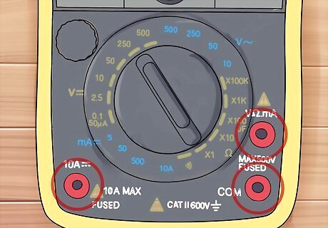
Read the port labels. Most multimeters have three ports or holes. Sometimes, the ports will be labeled with symbols that match the symbols described above. If these symbols are unclear, refer to this guide: The black probe always goes into the port labeled COM for common (also called the ground. (The other end of the black lead always connects to the negative terminal.) When measuring voltage or resistance, the red probe goes into the port with the smallest current label (often mA for milliamps). When measuring current, the red probe goes into the port labeled to withstand the amount of expected current. Typically, the port for low-current circuits has a fuse rated to 200mA while the high-current port is rated to 10A.
Reading an Analog Multimeter Result
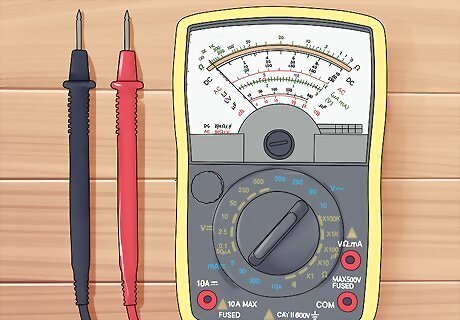
Find the right scale on an analog multimeter. Analog multimeters have a needle behind a glass window, which moves to indicate the result. Typically, there are three arcs printed behind the needle. These are three different scales, each of which is used for a different purpose: The Ω scale is for reading resistance. This is typically the largest scale, at the top. Unlike the other scales, the 0 (zero) value is on the far right instead of the left. The "DC" scale is for reading DC voltage. The "AC" scale is for reading AC voltage. The "dB" scale is the least used option. See the end of this section for a brief explanation.
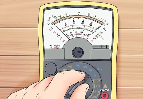
Make a voltage scale reading based on your range. Look carefully at the voltage scales, either DC or AC. There should be several rows of numbers beneath the scale. Check which range you have selected on the dial (for example, 10V), and look for a corresponding label next to one of these rows. This is the row you should read the result from.
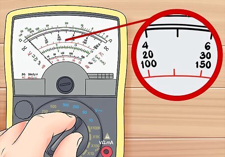
Estimate the value between numbers. Voltage scales on an analog multimeter work just like an ordinary ruler. The resistance scale, however, is logarithmic, meaning that the same distance represents a different change in value depending on where you are on the scale. The lines between two numbers still represent even divisions. For example, if there are three lines between "50" and 70," these represent 55, 60, and 65, even if the gaps between them look different sizes.
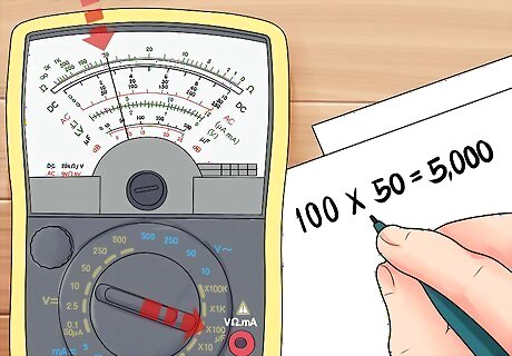
Multiply the resistance reading on an analog multimeter. Look at the range setting that the dial of your multimeter is set to. This should give you a number to multiply the reading by. For example, if the multimeter is set to R x 100 and the needle points to 50 ohms, the actual resistance of the circuit is 100 x 50 = 5,000.
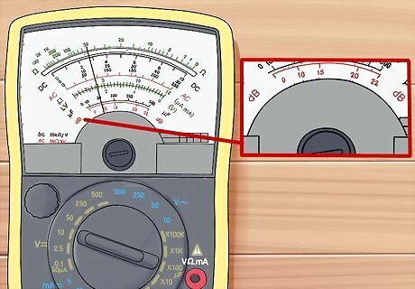
Find out more about the dB scale. The "dB" (decibel) scale, typically the lowest, smallest one on an analog meter, requires some additional training to use. It is a logarithmic scale measuring the voltage ratio (also called gain or loss). The standard dBv scale in the US defines 0dbv as 0.775 volts measured over 600 ohms of resistance, but there are competing dBu, dBm, and even dBV (with a capital V) scales.
Troubleshooting
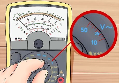
Set the range. Unless you have an auto-ranging multimeter, each of the basic modes (voltage, resistance, and current) has several settings to choose from. This is the range, which you should set before you attach the leads to the circuit. Start out with your best guess for the value which is just above the closest result. For example, if you expect to measure around 12 volts, set the meter to 25V, not 10V, assuming those are the two closest options. If you have no idea what current to expect, set it to the highest range for your first try to avoid damaging the meter. Other modes are less likely to damage the meter, but consider the lowest resistance setting and the 10V setting your default.
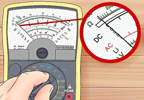
Adjust to "off the scale" readings. On a digital meter, "OL," "OVER," or "overload" means you need to select a higher range, while a result very close to zero means a lower range will give more accuracy. On an analog meter, a needle that stays still usually means you need to select a lower range. A needle that shoots to the maximum means you need to select a higher range.
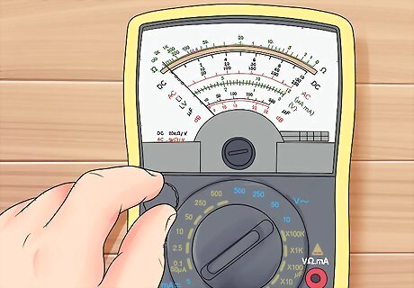
Disconnect the power before measuring resistance. Turn off the power switch or remove the batteries powering the circuit in order to get an accurate resistance reading. The multimeter sends out a current to measure the resistance, and if additional current is already flowing, this will disrupt the result.
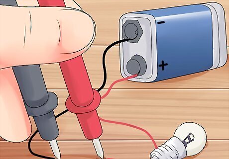
Measure current in series. To measure current, you'll need to form one circuit that includes the multimeter "in series" with the other components. For example, disconnect one wire from a battery terminal, then connect one probe to the wire and one to the battery to close the circuit again. Gain confidence using a multimeter. "I am new to working with electricity, and I found multimeter settings very confusing at first. But this article clearly explained how to interpret the dial markings and showed me where to place the different probes. After some practice guided by these tips, I can now confidently use a multimeter to test voltage, current, and resistance." - Jimmy R. Decode perplexing abbreviations. "All the VACs and mVAs on my multimeter dial seemed like nonsense abbreviations to me when I was starting out. This breakdown of the letter symbols and units of measurement helped me finally make sense of it all. Now, those cryptic labels are no longer intimidating." - Nickolas G. Troubleshoot reading issues. "I bought an analog multimeter at a garage sale, but some of the readings were odd or inconsistent. The troubleshooting advice here helped me figure out problems like incorrect range settings and calibration needs. After following these steps, my secondhand meter now works perfectly." - Tim G. Build electrical know-how from scratch. "As someone with very minimal electrical understanding, the terminology and concepts here were invaluable. By walking through how to test voltage, resistance, etc., in simple terms, this article built up my knowledge enough to start developing real competency. I'm amazed by how much I've learned!" - Jake P. Did you know that wikiHow has collected over 365,000 reader stories since it started in 2005? We’d love to hear from you! Share your story here.
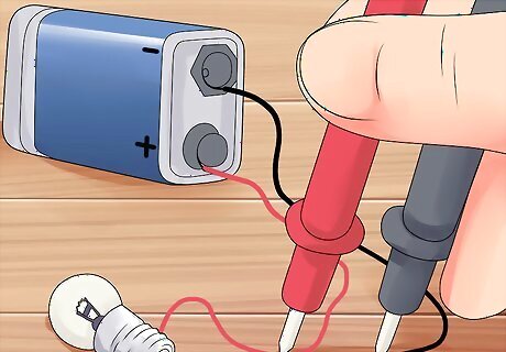
Measure voltage in parallel. Voltage is the change in electrical energy across some part of the circuit. The circuit should already be closed with current flowing, then the meter should have the two probes placed at different points on the circuit to connect it "in parallel" with the circuit. This must be done carefully to avoid discrepancy.
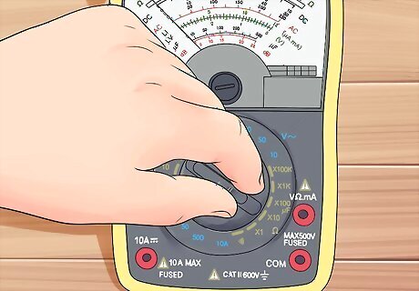
Calibrate ohms on an analog meter. Analog meters have an additional dial, used to adjust the resistance scale and typically marked with an Ω. Before making a resistance measurement, connect the two probe ends to each other. Turn the dial until the ohm scale reads zero, to calibrate it, then conduct your actual test.


Comments
0 comment