views
Pre-Assembling Necessary Components
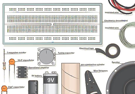
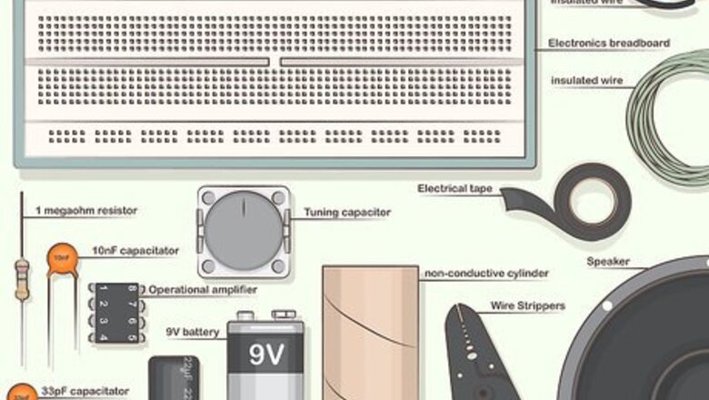
Gather your supplies. You likely already have many of the parts you’ll need for this project, excluding some of the electrical components. These can be bought at most hardware stores, home centers, and electronics stores. You’ll need: 1 megaohm resistor (x1) 10nF capacitor (x1) 15–20 inches (38–51 cm) of red insulated wire 15–20 inches (38–51 cm) of black insulated wire 45–60 feet (14–18 m) of 26 AWG (0.4 mm) enamelled wire (for the inductor) 200pF variable tuning capacitor (160pF will do. Up to 500pF works) 22uF electrolytic capacitor, (10v or higher) (x1) 33pF capacitor (x1) 50–100 ft (15–30 m) insulated wire (any color; for the antenna) 9-volt battery (x1) Electronics breadboard Electrical tape Operational amplifier, type 741 or equivalent (also called an op-amp; x1) Toilet paper tube, or small, non-conductive cylinder, 1.75–2 inches (44–51 mm) in diameter (glass bottle, cardboard/plastic tube, etc.) Speaker Wire strippers (or a similar item, like sharp scissors or a knife) Small knife or medium grit sandpaper
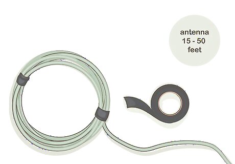
Make an antenna. The antenna is one of the simplest parts of a homemade radio: all you need is a long piece of wire. Ideally, the wire should be 50 feet (15.2 m) long, but if you don’t have that much, you can use as little as 15 or 20 feet (4.6 or 6.1 m). When choosing wire for your antenna, prioritize small diameter insulated wire (like ones in the 20- or 22-gauge), as these work best. Boost the reception of your antenna by looping its insulated wire into a coiled circle. You can keep the coil from unraveling with zip ties or electrical tape. Loop 50 feet (15.2 m) of wire about 5 times.
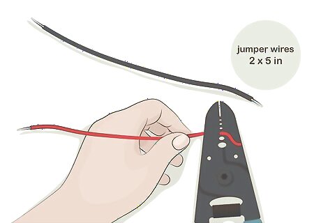
Cut and strip jumper wires. Jumper wires will connect components installed on the breadboard later. Cut one piece of black wire and one piece of red wire so that each is about 5 inches (12.7 cm) long. Use wire strippers (or a sharp knife) to remove about 0.5 inches (1.3 cm) of insulation from both ends of each piece of wire. Jumper wires can always be cut down to size if they turn out to be too long, so you may want to cut these a little on the long side at first.
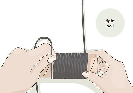
Make a coil to serve as an inductor. When you wrap wire around a cylinder with no space in the windings of the wire, it allows the wire to pick up radio waves as electromagnetic energy. This process sounds complicated, but making one is simple. Wrap 90 turns of enamelled wire into a tight coil around a cylinder 1.75 to 2 inches (44 to 51 mm) in diameter. Start winding your inductor at one end of the cylinder. Leave about 5 inches (12.7 cm) of slack where you fasten the wire with electrical tape to the lip of the cylinder. Wrap leaving no gaps in the windings. Aim for cylinders 1.75 to 2 inches (44 to 51 mm) in diameter. Avoid metal cylinders, because metal will throw off your signal.
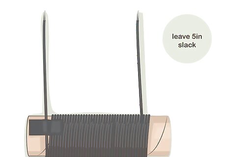
Wrap the cylinder completely to finish the inductor. The more windings your inductor has, the more inductance it has and the lower the frequency it will tune to. Continue wrapping until the whole cylinder is completely coiled with wire. Fasten the end with electrical tape, then measure another 5 inches (12.7 cm) of slack and cut the wire off at this point. Since the wire is covered with enamel, scrape the ends with a small knife to reveal 0.5 inches (1.3 cm) of bare copper so that we can connect it to the circuit. Alternatively, use medium sandpaper to sand the ends. The windings of your inductor can also be held in place with a liberal application of hot glue or a similar adhesive.
Wiring the Electrical Components
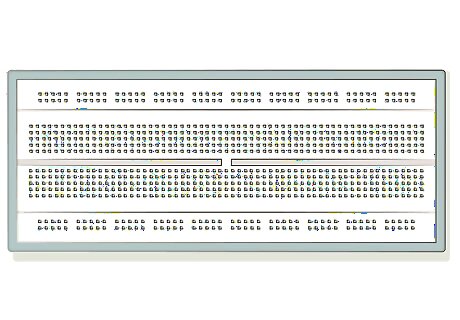
Position the breadboard. Lay your breadboard on the table in front of you lengthwise, so its long edge faces you. Which side faces up won’t influence how the breadboard works. The five holes in a column are electrically connected to each other, but not to any other column. Circuit components (like capacitors and resistors) are connected by being inserted into adjacent holes in a column on the breadboard. There is one exception to the connections on a typical breadboard: the long, connected rows at the top and bottom of it connect left-to right, not up-and-down like the rest of it. There are usually two rows on the top and two on the bottom, we will use only one row on the top and one row on the bottom.
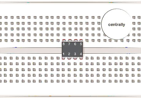
Place your op-amp on the breadboard. Notice that the op-amp has a small semi-circular divot on one edge, which is used to orient it properly. If there is no divot, there should be a small circular depression or dot on one corner. Hold the op-amp so that the divot or dot is on your left. The printed logo, letters and numbers on the device are the right way up when viewed this way. Most breadboards have a long trough running across the middle, separating the board into two equal halves. Place your op-amp (with the divot on the left) centrally on the board so that four pins are on one side of the trough and four are on the other. This will allow an uncluttered layout, with the input (the antenna and tuning capacitor) on one side of the breadboard and the output (the speaker) on the opposite side. The pins of amplifiers are numbered. To identify the pins, place the divot the left of you, pin 1 is the first pin on the left of the bottom row. Sometimes in addition to, or instead of, the divot, pin 1 has a circular depression or dot above it. The pins are numbered consecutively from 1 starting on the bottom row and continue counter-clockwise on the other side of the device. Confirm the numbering of the legs of the amplifier after installation is as follows: on the bottom row, moving left to right: 1, 2, 3, 4. From the leg opposite 4, moving right to left: 5, 6, 7, 8. The only pins used in this radio are: pin 2 = inverting input pin 4 = V- pin 6 = output pin 7 = V+ It is important not to reverse the polarity to the op-amp as it will destroy it. The op-amp is now oriented so that the top and bottom row match the polarity of the V+ and V- pins, when they are connected to the battery later. This layout avoids crossing the jumper wires and possibly causing a short circuit.
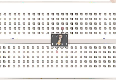
Put your 1.0M Ohm resistor over the op-amp. Current flows both ways over a resistor, so you don’t have to worry about its orientation on the board. Place one lead into the hole directly above the op-amp’s 6 pin. The opposite lead should be connected to pin 2 of the op-amp.
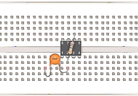
Place the 10nF capacitor. Insert the short lead of the 10nF capacitor into the hole directly below the connecting lead of your 1.0M Ohm resistor in the bottom row of op-amp pins. Next, place the long lead of the 10nF capacitor in a hole four columns to the left.
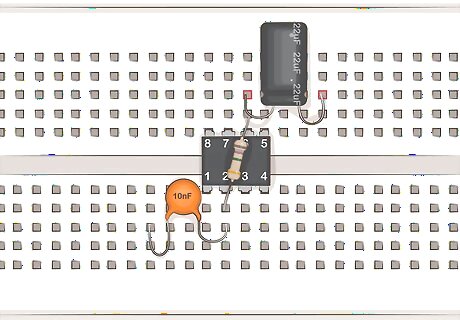
Hook up the 22uF electrolytic capacitor. Stick the short lead (negative side) of the 22uF capacitor in the hole directly above the lead connecting your 1.0M resistor to the top row of op-amp pins. The long lead can be put into a hole four columns to the right of the short lead. Electrolytic capacitors only accept voltage going in one direction. Electricity must enter in through the shorter lead. Applying voltage incorrectly can cause the capacitor to fail in a puff of smoke.
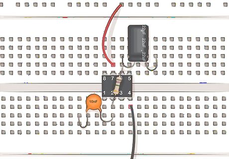
Add the jumper wires to the circuit. Use the red jumper wire to connect the hole directly above the 7 pin of the op-amp and the nearest free hole of the long, connected rows at the top. The black jumper wire connects pin 4 of the op-amp to the nearest free hole of the bottom, long, connected rows.
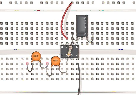
Place your 33pF capacitor. In the hole above the lead for your 10nF capacitor that isn’t yet connected anything, insert one lead for your 33pF capacitor. The other lead of the 33pF capacitor can go in an empty hole four columns to the left. This capacitor, like the first one you placed, isn’t polarized, so current can pass through it in both directions. It won’t matter which lead goes in which spot.
Finishing the Radio
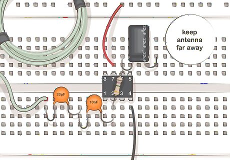
Attach the antenna. The antenna, yet unused until this point, is now ready to attach. Insert one end of the antenna into the hole directly above the empty lead of the 33pF capacitor. This is the same lead you just placed out of the way four columns away to the left. You can improve reception by spooling the wire of your antenna across the room as far as possible, or by winding it into a coil as described in the step on making the antenna.
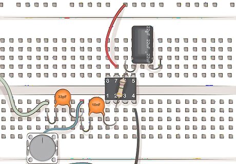
Connect your variable capacitor. Insert one lead of the variable capacitor into the hole above the rightmost lead of the 33pF capacitor. The other lead connects with the black jumper wire in the long, connected row at the bottom.
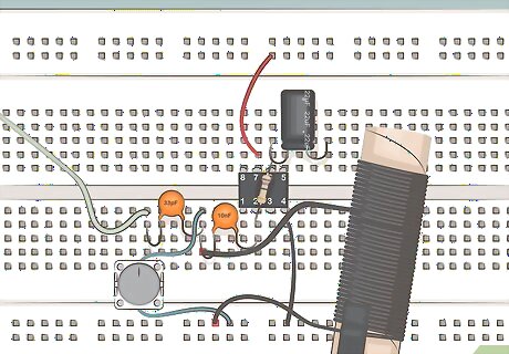
Attach the inductor coil. Use the 5 inches (12.7 cm) of slack on either side of the coil to fasten it with the variable capacitor and black jumper wire in the long, connected bottom row. The remaining lead attaches at in the hole below the junction of the variable capacitor, the 10nF capacitor and the 33pF capacitor.
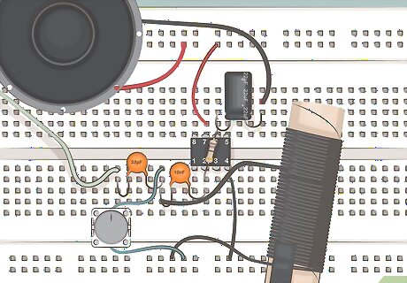
Plug in the speaker. Place your speaker on the table to the right of the variable capacitor. The red lead goes into the topmost row of the board to connect with the red jumper wire. The black lead goes into the hole directly above the unused lead of your 22uF electrolytic capacitor, on the right side of the capacitor. In many situations, you’ll need to untwist the wires for the black and red leads attached to your speaker so they can be tied in to the radio circuit.
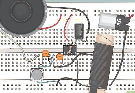
Attach your power source. Now that your circuit is finished, all it needs is some juice. Use electrical tape to attach wires to the positive and negative sides of the 9-volt battery. Then: Add the positive wire (usually red) to any hole on the topmost row of the breadboard so it connects the speaker and the red jumper wire. Add the negative wire (usually black) to any hole on the bottommost row of the breadboard to supply the black jumper and variable capacitor with current.
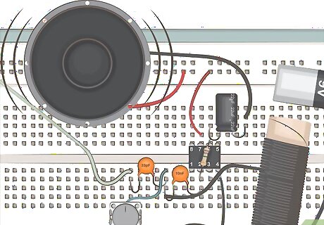
Listen to the speaker for noise. Once the circuit has power, the electricity will begin to flow to the amp and the speaker. The speaker should now be making sound, though it might only be faint noise or static. This is a good indication that all of your components are correctly connected.
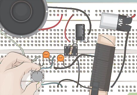
Turn the variable tuner to adjust the frequency. Turn the variable tuner slowly to shift the frequency your radio is reading and find audible radio stations. The further away from AM radio stations you live, the weaker the signals will be. Be patient and turn the knob slowly. With a little patience, it’s likely you’ll be able to pick up an AM radio station.
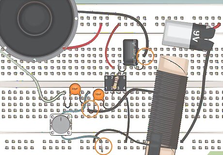
Troubleshoot the circuit. Circuits can be touchy, and many require troubleshooting, especially if this is the first circuit you’ve ever built. All leads need to be firmly inserted into holes, and each part of the circuit needs to be hooked up in the right fashion for it to operate. Sometimes you may have thought that you’ve pushed the lead all the way in to the board without it actually making a good connection. Inspect your connections on the breadboard to see if you have not connected a component in an adjacent column. The adjacent columns are not connected, therefore that component will not be connected to the others and may even be connected to the wrong item. The rows at the top and bottom on the breadboard are separate, make sure that the holes where the jumper wires are plugged in belong to the same row, not adjacent rows. Some breadboards have the top and bottom rows split into a left side and a right side. This is used when there are 2 different voltages in a circuit. In this radio, there is only one voltage is used. If the jumper wires are connected such that one is in the left side of a row and one is in the right side of a row, the radio will not work. The solution is to connect the jumpers in the same group of 5 holes of the same row, or to bridge the two rows with a small jumper wire at the middle of the rows. Adjust connections until you can hear audio when power is supplied. If this fails to work, you may need to rebuild the circuit from scratch.


Comments
0 comment