
Getting Setup
Open the building Operations Graphics editor. Locate and open the graphics editor on your desktop or under the Build Operations folder in the start menu.
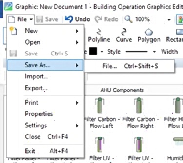
Save the file and name it. In the top right corner, select File drop down menu and select Save As… Then choose the file destination and name. Graphics Step 2.2.jpg
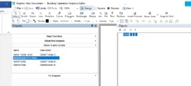
Drag and drop Global scripts into TGML. Open the “Snippets menu”, select the GlobalScripts and drag and drop it onto “TGML” on the right-side pop-up menu. Graphics Step 3.1.jpg

Create new layer with title (AHU). Right click on TGML and click add new Layer. Name it “AHU” which stands for Air Handling Unit.
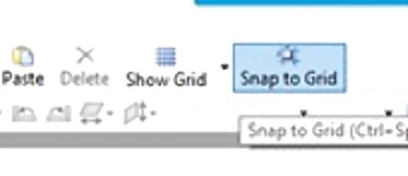
Set snap to grid and show grid size. Click on “Snap to grid button” and then the drop down menu in between that snap button and show grid button, select 20 pixel. Graphics Step 5.1.jpg
Ductwork and Equipment
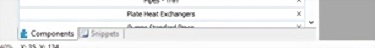
Open component menu. Open the components menu on the left side menu. The button is at the bottom of the screen. Graphics Step 6.1.jpg
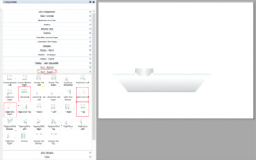
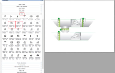
Select Supply ductwork. Select the “Duct – Supply” Tab, drag and drop Open end left, T up, horizontal, Open end right, in that order and place them in the desired location. Graphics Step 7.3.png
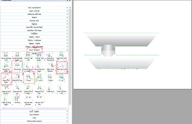
Select Extract ductwork. Select the “Duct – Extract” tab, drag and drop Open end left, T down, Horizontal, and then open end right, in that order and place them in an appropriate location. Graphics Step 8.png
Select the ventilation equipment. Select AHU Components tab and select the required equipment. Usually a filter, 3 dampers and 2 fans, which are placed in the following locations. Graphics Step 9.2.png
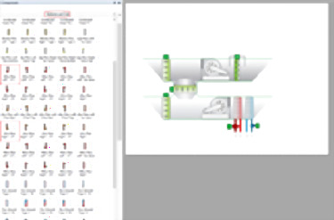
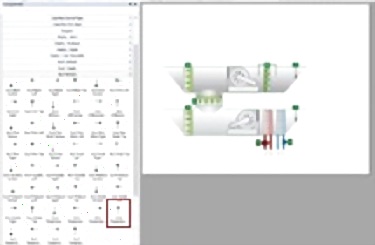
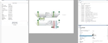
Drag and drop temperature equipment, heating coil and cooling coil. Select “Batteries and Coils” tab. Drag and drop the heating coil and cooling coil per engineer’s instructions and place them in proper locations. Graphics Step 10.3.png
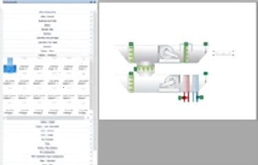
Place sensors in appropriate locations. Select “Duct Sensors” Tab. Drag and drop all sensors located in the ductwork and place them in proper location between the equipment. Graphics Step 11.1.jpg
Text Information
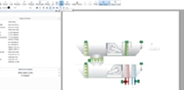
Select the “Display - Analogue” menu. Select analogue single line Text, 100 W. Drag and drop to its location. Graphics Step 12.1.jpg
Locate the Tooltip under Snippets. Drag and drop it onto the text box that was just created. Select the text box, here you can edit the text color and background color. Graphics Step 13.1.jpg
Select the Text button in the upper menu. Create the text box. Click near the top exhaust ductwork and type Room Temperature. You can label all equipment and sensors this way. Graphics Step 14.1.jpg
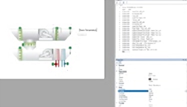
Explore Text properties. Select the text and explore the exposed properties, here you will be able to see the Font Family, size and style. You can alter all of them here. Graphics Step 15.1.jpg


Comments
0 comment